Guest: Bart
Using "shader_enable_corner_id()" for 3D particles
Hi all,
I am Bart Teunis, also Wisebart or simply Bart in some places. I’m a longtime user of GameMaker, going back to somewhere around 2002. In the last years I’ve been using GM extensively, mostly trying to get built-in things to work in 3D. I also wrote a couple of Blender exporters for it. More recently, I joined YoYo Games as a technical writer and am now one-half of the tech writing team doing the documentation.
I wrote a couple of articles for GM Shaders in the past, and it’s a pleasure to be asked by Xor to write another one.
Today, let’s explore how shader_enable_corner_id can be used in the vertex shader for particles, 3D billboarding, z-tilting, and more! Let’s jump in!
Drawing Things in GameMaker
First, let’s look at how you can draw things in GameMaker. There are several built-in functions that you can use for this. Most of them are named draw_*, but there are some exceptions such as part_system_drawit. All of these allow you to draw things:
/// Draw Event
draw_sprite(sprite_index, image_index, x, y);
What this does is the following:
Place the sprite with its origin at the room’s origin.
Move (translate) it to (x, y).
Apply the world matrix. Since we didn’t set any, it’s an identity matrix, and nothing changes.
Note: The world matrix deserves a whole tutorial on its own, but in short it’s a transformation that can be applied to anything you draw, allowing you to rotate, scale, translate, or skew it. This is rarely used in 2D, but in 3D this is a fundamental tool for placing or moving your models.
To turn that sprite upright to draw it “in 3D”, you can set the world matrix so the sprite is transformed:
/// Draw Event
var _mat = matrix_get(matrix_world);
matrix_set(matrix_world, matrix_build(x, y, 0, 90, 0, direction+90, 1, 1, 1));
draw_sprite(sprite_index, 0, 0, 0);
matrix_set(matrix_world, _mat);
Note that the sprite is now drawn at an (x, y) position of (0, 0), and the (x, y) offset is applied by the world matrix! This is necessary to avoid the sprite ‘orbiting’ around the room origin at(0, 0). In this case, the transforms are the following:
Place the sprite at the room origin.
Apply the world matrix:
Apply the rotation 90 degrees about X, followed by the rotation of direction+90 about Z (the order of operations for matrices built with
matrix_buildis YXZ).Move (translate) it to (x, y) (z is set to 0 to keep things simple).
This is the order that you need: first, rotate the sprite relative to its origin position, then translate it to its final position.
Putting draw calls between matrix_set’s like this is a quick and easy way to turn anything that you draw “into 3D” (together with setting a proper perspective projection). But you run into an issue when you try to do this with all particles in a particle system:
// Draw Event
var _mat = matrix_get(matrix_world);
matrix_set(matrix_world, matrix_build(x, y, 0, 90, 0, direction+90, 1, 1, 1));
part_system_drawit(ps, 0, 0);
matrix_set(matrix_world, _mat);
There’s a bit of an issue here if you look at what happens:
Place all particle shapes at the room origin and move them to their (x, y) positions. These coordinates are written to the vertex buffer by GameMaker.
Apply the world matrix:
Apply the rotations to all particles drawn by
part_system_drawit.
End up with a wrong result.
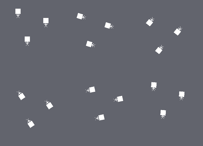
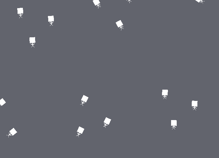
The particles are already moved to their (x, y) positions before having the rotation applied! So the order here is: translate first and only then rotate. That’s not what’s needed.
Comparing the two:
So this won’t work to turn individual particles upright to “turn them into 3D”. Or could there perhaps be some other way? To come up with a workaround, we need to learn a bit more about what happens when GameMaker draws things!
Vertex Buffers and Formats
All data that GameMaker sends to the GPU for drawing is stored in vertex buffers. A vertex buffer stores, as its name says, information on vertices (plural of vertex). A vertex is basically a single point of a shape, that has a position by default and that you can attach extra information to, such as a blend color, a normal, a vertex index, a vertex group, etc.
You submit a vertex buffer to the GPU for drawing using vertex_submit. The second argument, primitivetells the GPU how to interpret the data in the vertex buffer (how to connect the dots): pr_pointlist treats every vertex as a point, pr_linelist draws a line for every pair of vertices, and pr_trianglelist draws a triangle for every three vertices. You’ll usually use pr_trianglelist. (There are also the strip and fan varieties that are less interesting)
For the built-in draw functions, GameMaker itself creates the vertex buffers behind the scenes. Unfortunately, though, the format that it uses for most of its drawing (as listed in the Manual under Guide To Primitives And Vertex Building) is a bit limited:
vertex_format_begin();
vertex_format_add_position_3d();
vertex_format_add_colour();
vertex_format_add_texcoord();
my_format = vertex_format_end();
There is no “vertex index” in here, or a “sprite_index” or “particle index”. Also, as explained above, GameMaker adds the position of the sprite or particle to each vertex’s position.
So a first limitation is that it’s impossible to uniquely identify vertices belonging to the same group or primitive or transform them together. If there’d somehow be a way to find a shared point between vertices of a quad (two triangles that make up a rectangle) it’d at least be possible to manipulate them with respect to their common reference point: the center of the quad they belong to! (sprite, particle, etc.)
shader_enable_corner_id
The way to make GameMaker add some ‘bits’ of information to each of the vertices that allow you to work out that common point in the vertex shader is the function shader_enable_corner_id.
The GameMaker Manual has the following to say about it:
This function enables the use of corner IDs in shaders.
It sets a global state for all shaders being used where, when enabled, the shader "steals" 2 bits from the input colour values; one from the lowest bit of the red colour value, and one from the lowest bit of the blue colour value. These values can then be recovered in the shader to work out which vertex you are dealing with (i.e. which corner).
What this means is that GameMaker will use (read: overwrite) the lowest bit of the red and blue component of the color to store the corner ID. The reason you can get away with this is – in short – that the lowest bit of an 8-bit color component only contributes so little to the final color that you won’t notice it anyway; visually you’ll see no difference between e.g. make_color_rgb(255, 0, 0) and make_color_rgb(254, 0, 0). (for a detailed explanation, see my older GMC forum post on this, which is still relevant: Explanation of Corner ID)
Two bits allow for 2 x 2 = 4 combinations, which is the exact number needed to index all corners of a quad (e.g. a sprite):
To make GameMaker add corner IDs you need to add the following line of code before calling any draw functions that make use of it:
shader_enable_corner_id(true);Verifying the Values of the Corner IDs
All this is interesting, but how could you verify this yourself (if you wanted to)?
First of all, as mentioned on the manual page, the two bits can be retrieved as follows:
vec2 rem = mod(in_Colour.rb * 255., 2.);    // Note that b gets assigned to g!
int corner_id = int(dot(vec2(1., 2.), rem));
The first line of code multiplies the red and blue components of in_Colour by 255. to bring their values - floating point values ranging from 0. to 1. - into the range 0. - 255. (inclusive) and then calculates the remainder of a division by 2. This remainder gives the lowest bit, which is exactly what you need! All this is done using vec2s, so you get both bits at once in the vec2 variable rem. The second line of code uses a dot product to get the value of the corner ID in a compact way. The dot product really just does the following:
int corner_id = int(1. * rem.r + 2. * rem.g);You now have the two ‘bits’ that make up this final value of the corner ID in rem. They can be passed to the fragment shader to visualize them. In order to get them there, you need to add a varying to pass that data. To keep things simple, red is mapped to red, and blue is mapped to blue:
// Vertex Shader
varying vec3 v_corner_bits;  // Define an additional varying (a vec3 so you don’t need to use individual components in the FS anymore)

void main() {
    // Other code here…
    // …

    v_corner_bits = vec3(rem.r, 0., rem.g);  // Assign g back to b here!

    // ...
}
// Fragment Shader
varying vec3 v_corner_bits;
void main() {
gl_FragColor = vec4(v_vCorner, 1.);
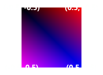
}The output for a sprite - or anything else that GameMaker draws using a quad, really! - is the following:
In this image, you start to see the pattern. The top-left corner is all black, this indicates that both the blue and red components are 0 there. The top-right corner is pure red, so here the red component must be 1 and the blue one 0. The bottom-right corner is pure blue, so here the red component must be 0 and the blue one 1. Finally, the bottom-left corner is purple, which indicates that both red and blue must be equal to 1 here.
Summarizing all that you could say that the corner ID starts out at 0 in the top-left corner, then increases clockwise:
Calculating the Center
With this information, you can now get the center of the triangle and/or quad this vertex belongs to! At least if you know the dimensions and when the triangles or quads aren’t rotated randomly. So now, even though you still don’t know which triangle or quad the vertices in the vertex shader belong to, you can get their common origin! Once you have that, the vertices can be transformed with respect to that! (or to any other point that you’d like to use as the origin)
For a 1x1 pixel sprite, the offset x and y from the center are always 0.5, with or without a minus sign:
For shapes of a different size, you need to send another important piece of information to the shader: its width and height. This brings up another limitation of this ‘trick’: all quads in the vertex buffer need to have the same dimensions.
Or, you need a bit more information to be able to use different dimensions in a single vertex batch.
It’d be nice if the array of offsets could be defined as a constant array in the vertex shader. Unfortunately, these are not supported in GLSL ES. The clean alternative is to pass them in via an array uniform instead:
// Create Event
arr_offsets: [
        -0.5, -0.5,   // Corner ID 0
         0.5, -0.5.,  // Corner ID 1
         0.5,  0.5,   // Corner ID 2
        -0.5,  0.5,   // Corner ID 3
]
uni_offsets = shader_get_uniform(sh_corner_ids, "u_offsets");

// Draw Event
shader_set_uniform_f_array(uni_offsets, arr_offsets);
// Vertex Shader (using GLSL ES)
uniform vec2 u_offsets[4];Indexing the Offsets Array
To look up the offset for the current corner ID, you use that ID as the index in the offsets array. You might be tempted to write the following in the vertex shader:
vec2 offset = u_offsets[corner_id];At first, this seems to be all that is needed. And at least on Windows that is correct. But alas, it doesn’t work in all versions of GLSL ES. Some versions expect you to use a so-called “constant expression” for the upper bound of the loop, which is necessary because the compiler has to be able to ‘unroll’ the loop. This is currently the case on e.g. the GX.games target.
Loop Unrolling
Unrolling a loop means that the statements that you write in a loop are actually written out multiple times by the compiler in the final shader. The shader compiler writes all iterations of your loops. To be able to do this, it needs to know at compile time the exact number of times to write those statements.
In practice you can work around this limitation by providing a high enough constant upper bound and breaking out of the loop once you reach the index you want to look up:
vec2 offset = vec2(0.);
for(int i = 0;i < 4;i++) {
    if (i == corner_id) {
        offset = u_offsets[i];
        break;
    }
}
The compiler won’t have an issue with the above code since the upper bound is a constant at compile time. Still, you’re able to get the value at the index you need by breaking out of the loop. Problem solved!
Bringing it all Together
What seemed impossible at first, has now become possible: individual quads in a vertex buffer, having their positions in world space, can now be transformed about their center position!
Let’s see how this works by choosing a built-in particle shape and turning this into 3D billboarded particles (not a pixel, since its dimensions are known to be 1x1px). To keep things simple, let’s assume that all particles are the same shape so the size can be hard-coded in the vertex shader.
/// Create Event
shader_enable_corner_id(true);
arr_offsets = [
	-0.5, -0.5,
	 0.5, -0.5,
	 0.5,  0.5,
	-0.5,  0.5
];
uni_offsets = shader_get_uniform(sh_corner_ids, "u_offsets");

ps = part_system_create(ps_spheres);
part_system_position(ps, x, y);
part_system_automatic_draw(ps, false);

/// Draw Event
shader_set(sh_particles);
shader_set_uniform_f_array(uni_offsets, arr_offsets);
part_system_drawit(ps);
shader_reset();
/// Vertex Shader
attribute vec3 in_Position; // (x,y,z)
attribute vec4 in_Colour; // (r,g,b,a)
attribute vec2 in_TextureCoord; // (u,v)
varying vec2 v_vTexcoord;
varying vec4 v_vColour;
uniform vec2 u_offsets[4];
void main()
{
// The dimensions of pt_shape_sphere, hard-coded
float size = 61.;
// Get this vertex's corner ID
vec2 rem = mod(in_Colour.rb * 255., 2.);
int corner_id = int(dot(vec2(1., 2.), rem));
// Get the offset corresponding to the corner ID
vec2 offset = vec2(0.);
for(int i = 0;i < 4;i++) {
if (i == corner_id) {
offset = u_offsets[i];
break;
}
}
// The center can now be found
// Note: the vertex shader calculates the same value for all vertices of the same particle/sprite!
vec2 center = in_Position.xy - offset * size;
// Transform the particle here
// ...
// Assign the position and pass the varyings as usual
vec4 object_space_pos = vec4(center + offset * size, 0.0, 1.0);
gl_Position = gm_Matrices[MATRIX_WORLD_VIEW_PROJECTION] * object_space_pos;
v_vColour = in_Colour;
v_vTexcoord = in_TextureCoord;
}
/// Fragment Shader
// Identical to the default "passthrough" fragment shaderNext Steps
The next step is to support multiple shapes and/or sprites within a vertex batch. Finding out the exact particle dimensions of GM’s built-in particle shapes isn’t an obvious thing though. My first idea was to look into the runtime’s “cache” folder: it turns out that all shape images are stored as 64x64 PNG images. But GM crops them when it places them on a texture page. The dimensions can be found however with a convenient script (+shader): part_type_get_uvs.
With that knowledge, the next thing to figure out is the uv range that in_TextureCoord belongs to. This gives you an index in uniforms that you use to pass in data per particle shape or sprite, such as:
Per-particle-type/per-sprite dimensions
The origins of sprites, so those can also be taken into account
Anything else really!
Specifically to support particle system assets, a very useful function is particle_get_info. It gives you all the info you’ll ever need to send to the shader!
The Result
After adding all of the above, and extending the shader so it can draw the particles along GM’s built-in paths, the following is possible:
More Ideas and Limitations
Some other ideas have come to mind for this:
Quad ‘butterflies’: the vertices not on the diagonal can be moved up and down to create the effect of a butterfly’s wings flapping. So you can “butterfly-ify” GM’s built-in particles!
A layer begin script and a layer shader that automatically turns all sprites drawn on that layer into billboards. No more batch breaks caused by setting the world matrix for every sprite!
Pass additional textures to the shader, to add lighting, normals, etc.
…
Since this uses GameMaker’s built-in particle system, it cannot be customized that much. So there are limitations as well:
Some particle properties cannot be supported (e.g.
part_type_orientation,part_type_lifeandpart_type_deathto name a few), in particular theincrandwigglevalues of those.The vertex format could be optimized quite a bit, but you have no control over it.
The particle systems are updated on the CPU, which limits the number of particles you can use. With the recently added surface formats, particles could be done a lot more efficiently on the GPU. To keep the CPU free for other things.
Final Words
Getting the particles to work in “3D” (to a certain extent) has been another one of those interesting adventures with GameMaker. I quite honestly didn’t expect it could be taken this far. Though then again, it continues to surprise me what you can do with GameMaker!
My most recent jam game, Incoherent, shows the particles at work in an actual game setting. You can find a video about it on my YouTube channel, as well as videos about those other 3D experiments and jam games made with GM. All code that I publicly release can be found on GitHub. And perhaps I might start at one point with writing about other related GM things on that Substack that I now appear to have.
Thank you for reading!
Bart


