Mini: CRT
Breaking down the "Cathode-Ray Tube" effect
Hey folks!
Do you remember these old, fat, curved TVs?
These used to be everywhere and they gave our games a certain cozy feel. There’s something special about it. Maybe it’s just nostalgia, but in any case there’s gold here waiting to be tapped into.
Today will explore emulating that look, whether it’s for giving your game a more retro look, or just to understand how the tech works.
RGB Cells
Color CRT TVs have 3 electron guns for the red, green, and blue channels. These are effectively laser beams, which scan across the screen one pixel at a time. The red light hits the red phosphor, green hits the green phosphor, and blue hits the blue phosphor allowing for each channel to be independently controlled.
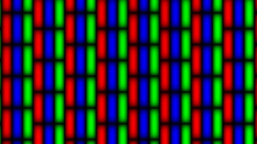
These pixel cells are arranged on a “shadow mask” typically like so:
Notice the staggering between cells, presumably to break up any blocky appearance. The black boundaries around these cells are also important as they help prevent illuminating the wrong cells. It’s essentially an error margin.
So let’s look into recreating this!
The first step is to get pixel coordinates:
//Compute pixel coordinates from the texture resolution uniform
vec2 pixel = v_vTexcoord * u_resolution;
Next, we can divide these into mask cells:
//RGB cell and subcell coordinates
vec2 coord = pixel / MASK_SIZE;
vec2 subcoord = coord * vec2(3,1);“MASK_SIZE” is a macro for the size of each cell in pixels making each “coord” unit one mask cell. The “subcoord” is for the RGB subcells. Since there are three per cell, we need to multiply the x-coordinates by 3.
Now we need to offset every other cell by half a unit to recreate the staggering pattern seen above:
//Offset for staggering every other cell
vec2 cell_offset = vec2(0, fract(floor(coord.x)*0.5));
Now we pick the RGB subcell using the subcoord’s x value. The first subcell is red, then green, then blue, so we can compute an index value from 0 to 2 and pick the channel using that value:
//Compute the RGB color index from 0 to 2
float ind = mod(floor(subcoord.x), 3.0);
//Convert that value to an RGB color (multiplied to maintain brightness)
vec3 mask_color = vec3(ind == 0.0, ind == 1.0, ind == 2.0) * 3.0;
If you output the resulting colors, you should get a similar pattern to the image shown above. Here’s how I compute the soft shading between the cells:
//Signed subcell uvs (ranging from -1 to +1)
vec2 cell_uv = fract(subcoord + cell_offset) * 2.0 - 1.0;
//X and y borders
vec2 border = 1.0 - cell_uv * cell_uv * MASK_BORDER;
//Blend x and y mask borders
mask_color.rgb *= border.x * border.y;
Now we could just multiply this with the base texture, apply this shader to the application surface, and call it good, but why stop here? We already have the cell coordinates so we should be pixelating the texture to match the cell size.
This is just rounding the cell coordinates (with the cell offset) and scaling back to pixel coordinates (divide by resolution for the texture coordinates):
//Pixel coordinates rounded to the nearest cell
vec2 mask_coord = floor(coord+cell_offset) * MASK_SIZE;
Chromatic Aberration
I think this looks even better when you shift the green channel separately:
//Chromatic aberration
vec4 aberration = texture2D(gm_BaseTexture, (mask_coord-ABERRATION_OFFSET) / res);
//Color shift the green channel
aberration.g = texture2D(gm_BaseTexture,    (mask_coord+ABERRATION_OFFSET) / res).g;
Feel free to try a few different offset values and shifting different channels to see what looks best to you. You can even do a 3-sample chromatic aberration, shifting the red, green, and blue channels individually, but I find the green offset was good enough for my needs.
Screen Curvature
If you want to add some distortion to give the illusion of screen curvature, you can do so by squishing the input texture coordinates before calculating the pixel coordinates. I particularly like this formula:
//Signed uv coordinates (ranging from -1 to +1)
vec2 uv = v_vTexcoord * 2.0 - 1.0;
//Scale inward using the square of the distance
uv *= 1.0 + (dot(uv,uv) - 1.0) * SCREEN_CURVATURE;
//Convert back to pixel coordinates
vec2 pixel = (uv*0.5+0.5)*res;
This is assuming you’re drawing to a surface and have your texture coordinates ranging from 0 to 1. A good “SCREEN_CURVATURE” will be between 0 and 0.1.
But this look is incomplete without a little vignette to spice it up!
Vignette
In a similar fashion to the cell shading, we can add some vignette by using the distance to the edges of the screen. Since the signed uv coordinates range from -1 to +1, squaring them makes them range from +1 to 0 in the middle to +1 again, in both the x and y axes. We need the gradient to be dark at the edges and bright in the middle, so we want 1.0 - uv*uv. Note: Normally we could assume this value would always be 0.0 or greater, but with screen distortion, this isn’t always the case.
Now we just multiply these two gradients together and put them to some small exponent (I like 0.4) to make the middle brighter and the vignette curve sharper (smaller values = sharper curves). Here’s my code:
//Square distance to the edge
vec2 edge = max(1.0 - uv*uv, 0.0);
//Compute vignette from x/y edges
float vignette = pow(edge.x * edge.y, SCREEN_VIGNETTE);
//Apply vignette
color.rgb *= vignette;
Pulsing
It’s looking pretty good so far. Another nice, rather subtle touch is to add some pulsing across the screen:
color.rgb *= 1.0+PULSE_INTENSITY*cos(pixel.x/PULSE_WIDTH + u_time*PULSE_RATE);This can be done as simply as doing a sine wave across the screen with the amplitude controlling the pixel brightness. These are my chosen values:
//Intensity of pulsing animation
#define PULSE_INTENSITY 0.03
//Pulse width in pixels (times tau)
#define PULSE_WIDTH 6e1
//Pulse animation speed
#define PULSE_RATE 2e1
This same method can also be used for vertical scanlines (without animating). Feel free to add scanlines if you wish!
Bloom
And finally, to complete the look, I highly recommend adding some bloom!
I’ve already written about bloom so to avoid redundancy, I’ll just leave a link here:
GM Shaders Mini: Bloom
Hi readers, Today, I want to talk about one of my favorite post-processing effects: Bloom. Bloom is used to make elements appear brighter and richer. We’ll explore a simple, old-school method and a more modern richer method: For comparison, here’s a cheaper type of bloom that was common in the late 2000s and early 201…
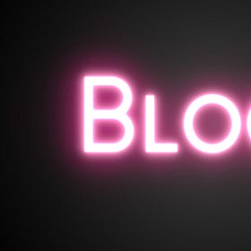
Here’s what it looks like with some subtle bloom added:
I put together a full ShaderToy demo including the CRT and bloom shaders, so feel free to check it out for a complete picture of how it all goes together.
Here’s the GM version.
Conclusion
CRT is a rather complex effect because it’s composed of many parts including RGB color masking, pixelation, chromatic aberration, screen curvature, vignette, pulsing, scanlines, and bloom. Hopefully, this tutorial helps mesh it all together so that it’s easier to approach. The best part about an effect like this is you can create many variations by using bits and pieces. Perhaps scanlines, chromatic aberration, and vignette effects are enough for one game. Maybe all you need is the RGB mask and pixelation?
With a little creativity, you can make it look entirely different to suit your particular needs. I recommend monochrome green for a retro hacker style!
Anyway, I hope you learned something new. Next week I have a special guest who has prepared something awesome, make sure to subscribe if you haven’t already!


I created a version of your shader on my website demonstrating WGSL shaders.
https://wgsl-shader-depot.vercel.app/samples/complexCRT
the source code would be nice in gm. There's many parts where you introduce a variable that isn't explained anywhere.
like what is res (i assume you were referring to u_resolution)
and texture() maybe it's the custom function example you wrote in a different article?
Trying to understand and follow but it's a bit hard to keep track. Still thanks for writing this