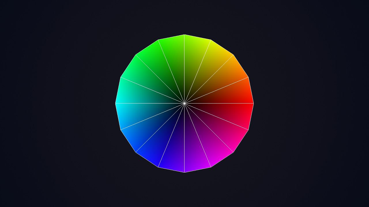
Vertex Shaders
An introduction to vertex shaders: when and how to use them
Good evening,
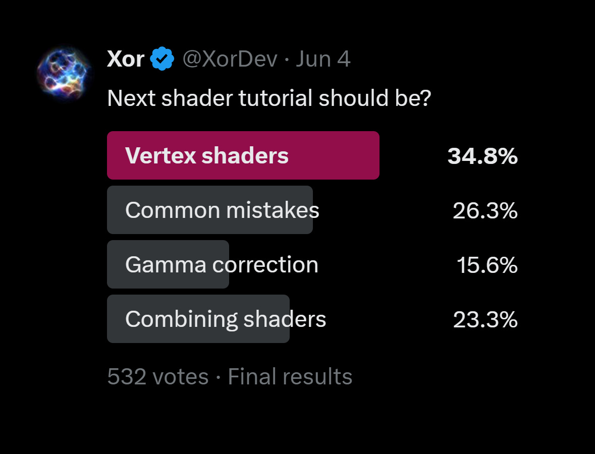
I ran a little poll on X to see what tutorials you guys were interested in and vertex shaders came out on top:
The majority of my shader tutorials have been focusing on fragment/pixel shaders, but today we’ll shift over to vertices and vertex shaders (when and how to use them).
They can be used to displace vertices (e.g. wind or wave shaders), optimize shader calculations and handle input data like surface normals.
Note: As of writing, we’re working with old school GLSL 1.0, so while the concepts are still relevant, the implementations may vary.
Rendering Pipeline
First, let’s make sure we’re on the same page here.
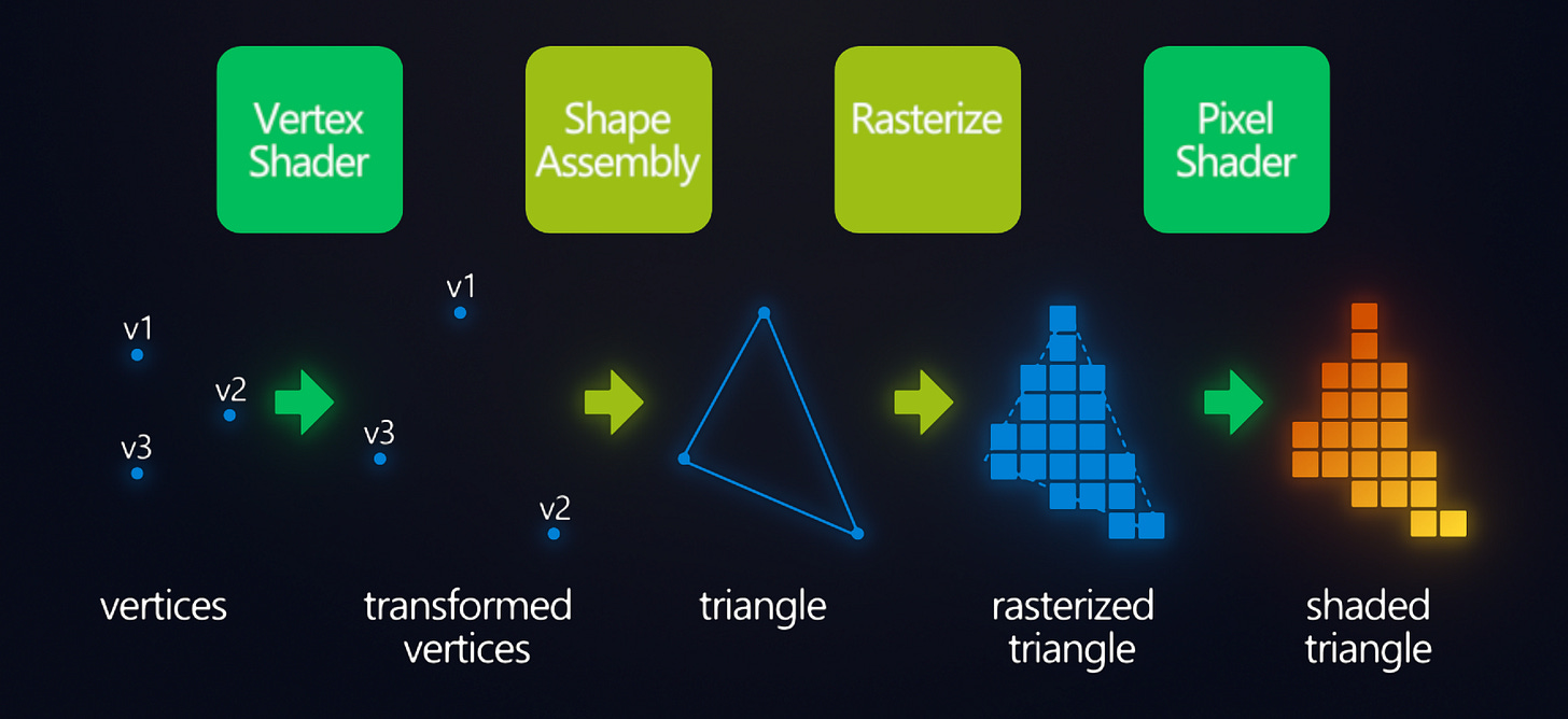
To briefly summarize the rendering pipeline, everything you draw starts as a series of points called vertices. These vertices are then assembled into primitives like triangles, lines or points. These get rasterized into fragments (pixels) and this is where the fragment shader is applied.
Everything you draw, a sprite, circle, rectangle, and even text, is composed of vertices. A sprite is drawn by using 4 vertices at the four corners of the sprite, using two triangle primitives to fill it in. The same goes for text, with each character being its own textured-quad (using the font sheet as its texture).
The vertex shader applies to the vertices before primitive assembly, allowing the vertex positions and the data the fragment shader receives, to be modified. That’s the quick overview that I wish I had when I started, like 10 years ago. Let’s get a little more specific about how the vertex shader handles data.
Attribute Inputs
Here’s the standard GameMaker GLSL vertex shader:
//Input vertex data
attribute vec3 in_Position;	//x,y,z
attribute vec4 in_Colour;	//r,g,b,a
attribute vec2 in_TextureCoord;	//s,t

//Data passed to fragments
varying vec2 v_coord;
varying vec4 v_color;

void main()
{
	//Object position with w=1 for transformations
	vec4 object_space_pos = vec4(in_Position, 1.0);
	//Set projection-space position
	gl_Position = gm_Matrices[MATRIX_WORLD_VIEW_PROJECTION] * object_space_pos;

	//Pass color and texture coordinates to the fragment
	v_color = in_Colour;
	v_coord = in_TextureCoord;
}
The attributes are the data that each vertex contains. The standard is vertex position, color and texture coordinates. Functions like draw_text() and draw_sprite() obviously need texture coordinates. Some functions like draw_rectangle() and draw_roundrect() actually work by using a default 1x1 pixel texture.
Other draw functions like draw_line() and draw_circle() have no texture coordinates and will silently fail if you try to draw them with a shader that expects them!
If that becomes an issue for you, you can always create a separate shader for each set of attribute inputs. If you’re ever building your vertex buffers, you can always add your own custom attribute data for each vertex (sometimes used in 3D for bone animations, or tangents, bitangents or baked vertex lighting):
If you add additional texture coordinates, you’d want to number the attributes “in_TextureCoord0”, “in_TextureCoord1”, etc. so that they get interpreted correctly. If you’re going for optimized rendering, you’ll want to keep the attribute data to a minimum, as it can use a lot of memory and slow down rendering. With large vertex buffers, it can make a big difference to reduce.
In newer versions of GLSL, attributes are replaced with “layout” qualifiers:
layout(location = 0) in vec4 color;Varying Outputs
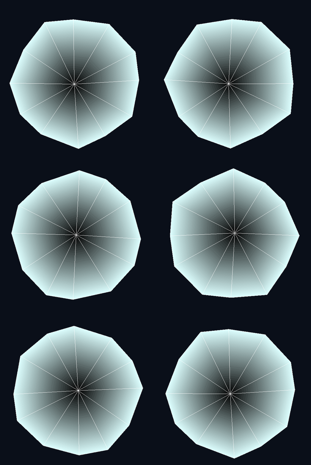
To pass the inputs like the vertex color to the fragment shader, you can use the “varying” qualifier (also later replaced with “layout”). Data passed this way will get linearly-interpolated across the triangle faces. For example, you can calculate lighting per-vertex instead of per-fragment:
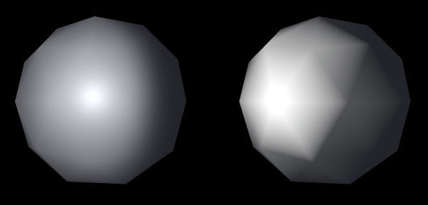
This gives a retro look and saves a bit of performance costs. Colors, texture coordinates and normals all get blended in the same way when you pass them to the fragment shader. Generally, if something can be calculated once per-vertex, then you should to save the GPU some work.
You can pass floats, float vectors and even matrices, but no ints or bools. I like to use the v_* prefix for my varying variables to keep them distinct, but they can be named however you like.
Transformations
You know how the fragment shader outputs fragment color via gl_FragColor?
Well, the vertex shader similarly has its own output, but for the vertex position on the screen. It expects projection-space coordinates which range from -1 to +1.
I already wrote about the vector spaces, so I recommend giving it a read if you haven’t yet:
The world matrix can be used to do most transformations like translation, rotation, stretching, skewing, etc. without needing to touch vertex shaders, but there are other transformations which are impossible to achieve without vertex shaders (especially in 3D).
For example, you can add a little sine waving to the position before converting it to projection space:
vec4 position = vec4(in_Position, 1.0);
position.xy += cos(position.yx/8. + u_time) * 12.;
gl_Position = gm_Matrices[MATRIX_WORLD_VIEW_PROJECTION] * position;
With a time offset, you can add some motion, and you got some ripples!
This technique can be used for water, wind, shockwaves and much more. Since the vertex shader happens before primitive assembly, it can actually be used to modify the area that the fragment shader applies to. Blurring fragment shaders can’t blur outside the primitive, but you could use the vertex shader to add padding around the original primitive. It’s a little outside the scope of today’s tutorial, but the idea is to use the texture coordinates and the texture coordinate range to find the edge direction and moving the vertices outward in that direction. Maybe I’ll write about that later if there’s a need.
Limits
There are some things that work in fragment shaders, but not in vertex shaders. You can’t share the same uniform in the vertex and fragment shaders. If you need the same value in both, you should pass two separate uniforms.
You can’t sample textures in the vertex shader. This is a limit of GameMaker. In theory, it could work using texture2DLod(sam,uv,lod), however GM doesn’t support it (it works on HTML5 strangely, but that’s it).
Derivative functions like dFdx/dFdy/fwidth wouldn’t make sense in a vertex shader context, but they do work well on varying variables in the fragment shader because each face’s derivative is computed separately without edge aliasing!
You can compute flat shading from the derivatives of the fragment position:
//Compute normal from fragment position derivatives
vec3 normal = normalize(cross(dFdx(v_pos), dFdy(v_pos)));
Conclusion
Vertex shaders are pretty cool. They don’t get a lot of attention, especially in 2D games, but they still have useful features to consider utilizing. The most powerful part, is being able to manipulate each vertex independently. Because this happens before the primitive assembly stage, you actually have control over where your fragment shader applies. You could expand the primitive, if you need to cover a greater area, or just distort it for effect.
Vertex shaders are also a great way to optimize your rendering. They can be used to reduce the amount of attribute data and can reduce the load on the fragment shader. Sometimes you might just want old-school stylized vertex lighting, and you can do that here as well. I hope that after reading this tutorial, you’ll have a more complete picture of how the GPU works and how to optimize rendering.
Extras
Here’s a 3D water shader I wrote a while back that uses the vertex shader for wave displacement and normal calculations:
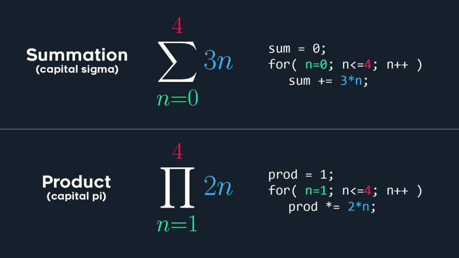
In case you missed it, Freya shared a math illustration that helps demystify some a couple of math symbols for my programming folks.
When you see summation or product, it can be helpful to think of them as for-loops.
That’s all I got for now. Thanks for reading and have a good one!


